Smoke analysis
Glow Plug system update, 6.9
There have been many glow plug system changes and redesign over the production run of the IDI engines. In fact, 83 trucks have two different wiring schematics. The old, screwed-in-the-head controller/sensor was undependable and frequently failed, and usually would seize in the head.
Reciently Ford has suggested that the old-style system be replaced with the new, intergrated system. The good news is, you can buy the integrated controller and a set of glow plugs for about the same price as you would pay for a replacement screw-in controller (from Ford). The bad news is you have to replace the glow plug harness.
You need the following parts to perform the update:
*This harness is now unavailable--use P/N F0TZ-9A451-A
Drill and tap two holes (1/4" USS) on the rear intake manifold bridge and mount the new controller there. If the truck has a turbo, you'll have to reposition the controller and fabricate a bracket and modify the harness to reach. Attach the controller ground to one of the intake manifold bolts. Replace all the glow plugs and remove the old engine harness, replacing it with the new one.
You can either leave the original controller in the engine, or remove it and install a pipe plug with teflon thread sealer.
Now the update gets a little tricky. You can either choose to use the original glow plug feed wires to supply voltage to the new controller by removing them from the glow plug power relay output terminal and installing them on the relay battery terminal, or you can overlay this circuit with a 6 foot 6 gauge starter or ground cable with two parallel 6 inch 14 gauge fuse links soldered to the end that attaches to the relay battery terminal (see tip below). I recommend the second because it by-passes any resistance problem areas in the original chassis harness and connector. Whichever way is acceptable as long as the old power relay is being used as a junction block. Remove the relay coil energize and ground wires.
![]() On trucks with a 6 pin chassis-to-engine harness connector and a "wait" light relay (early 83), unplug the wait light relay (under the dash below the diesel warning light module) and jumper pin 5 (BK/PK--from light) to pin 2 (O--to controller).
On trucks with a 6 pin chassis-to-engine harness connector and a "wait" light relay (early 83), unplug the wait light relay (under the dash below the diesel warning light module) and jumper pin 5 (BK/PK--from light) to pin 2 (O--to controller).
Remove the connector hardshell from the chassis and new engine harness and connect the ignition switch feed (R/LG) to the controller ignition wire (R/LG), the wait relay wire (O) to the wait light control wire (BK/PK) and the wires from the glow plug power relay (Y) to the controller power wires (Y)--unless you have over-layed the circuit as described below--and tape back any unused wires and connectors.![]()
The fuel heater and temp sender wires are on a seperate harness.
On trucks with an 8 pin chassis-to-engine harness connector and "wait" light powered by the glow plug power relay ("wait" light on whenever glow plugs have power; late 83-87), install the wait light power wire (B) on the power relay terminal opposite from the one being used as a junction for the controller battery feed. Install a jumper from the battery feed terminal to the relay coil energizing terminal. Remove the wait light control wire (BK/PK) from the engine connector and run a wire from it to the power relay ground terminal (this will cause the "wait light to be illuminated only when the controller grounds the power relay).![]() A Bosch-type ISO relay can also be used. Otherwise the "wait" light wire can be installed on the glow plug feed terminal of the controller and the light will come on every time the controller cycles.
A Bosch-type ISO relay can also be used. Otherwise the "wait" light wire can be installed on the glow plug feed terminal of the controller and the light will come on every time the controller cycles.
If the fuel heater is supplied from another harness, remove the fuel heater wire (DB) from the engine connector and tape it and the fuel heater connector back. If the heater is powered through the same connector, you need to remove the wire from the engine connector and reinstall it in the hole which had the BK/PK wire in it.
Plug the engine and chassis harnesses together and check for proper operation.
Stall after starting (especially after hot-soak/cool-down) then hard start
Air intrusion into the fuel supply system. Usually, the source of the fuel leak can be determined by the time from when the engine starts to when it stalls. On 6.9 engines with a firewall-mounted water separator, the engine will start and run for upto a couple of minutes before any air which may be in the separator reaches the injection pump. The 6.9 water separator is prone to leaks, both fuel and air. The best cure for this is to replace the OEM seperator with an aftermarket one (much cheaper--$30-$60 vs. $180), or remove it and its hoses and connect the line from the tank to the one running to the lift pump. Since it's not recommended to operate a diesel engine without a water separator, replace the fuel filter with the 7.3 type filter/water separator assembly. You can either purchase the header and sedimate bowl from Ford or a wrecking yard and install a new 7.3 filter. Another option is the Racor fuel filter/water separator kit. This kit contains a filter which fits on the original header and has a water sedimate bowl which screws onto the bottom (@ $35). The filter can also be purchased separately (@ $20), and you would want to keep a spare on hand as the replacement filter would not be available at your local parts store.
The 7.3 filter/water separator can develop fuel/air leaks at the fuel heater and restriced filter sensor or the filter drain (all three are servicable) and water in fuel sensor o-ring. The air bleed Schrader valve can leak on either filter.
The next common area for air leaks on both the 6.9 and 7.3 engines is at the injector return cap o-rings and hoses. This will cause the engine to stall after about 30 seconds of running if the air is able to travel into the fuel filter. On 6.9 engines the return line from the filter should be long enough to loop about four inches above the filter.
The 6.9 can be modified to have a check valve at the fuel filter return to prevent air from entering the filter. A 7.3 Econoline filter outlet fitting (E8TZ-9C402-A) can be installed in place of the original outlet fitting. An early 3/16" 7.3 filter return orifice with a "flapper" valve can be installed into the port ment for the E-van's restricted filter sensor.
On 7.3 engine the filter return orifice contains a check valve. This check valve is usually a rubber flap inside the fitting, and if this fails air is drawn into the filter as the fuel cools and contracts. This can be detected by removing the fitting and trying to blow through it from the hose barb end. If you are able to blow through it from this direction, it needs to be replaced. Seal the threads on the orifice with Loctite 515 Gasket Eliminator or PST. There are two different flapper valve orifices--3/16" and 1/4"--and the correct one needs to be used with the coresponding hose size or leaks may occur. Starting in 92 a 1/4" filter orifice was introduced without a flapper valve using a spring and plastic check ball. The spring-and-ball and flapper orifices are not interchangable; they have different headers. Also, the correct size return lines hose needs to be matched to the injector caps and the proper clamps used--not worm-gear, this will distort the hose; either OEM spring clamps or fuel injection system screw-and-band type. When replacing injector return o-rings on one injector, you should replace all on that cylinder head as they tend to leak after they have been disturbed. Use silicone dielectric grease to aid in reassembly and some times it helps to install a third o-ring between the return cap and injector line nut to keep the cap in place.
On the fuel supply lines at the filter inlet, filter outlet and injection pump inlet, there are seals which can allow air to enter the fuel system if they become deteriorated or dried out, even if there are no visible signs of fuel leakage. If there is a leak on the line between the filter and injection pump, the engine will seem to try to start, then become hard to start. Note that there are seals of the same type on the injection pump return line at the injection pump and at the return line collector fitting on the rear of the engine (some applications).
Less common areas for air leaks are the injection pump outlet check valve and the fuel lift pump, but both have been know to happen. Using clear hose on various sections of the fuel suppy and return systems can usually pinpoint the area of the air leak. Install the clear hose at the suspect areas, start the engine to purge any air, then allow to cool. Watch these hoses for large air bubbles or pockets when starting the engine to determine the origin of the air leak. Also allow the engine to come up to operating temperature to look for air leaks which may occur when the system is hot. These may migrate into the filter and cause a hard start concern.
Engine stalls at stops or when deprsessing clutch
Stalls returning to idle after snapping throttle open.
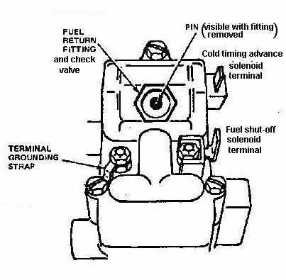
Injection pump problem caused by poor quality or contaminated fuel. Check for presence of water in the fuel--removal of the injection pump governer cover may be necessary to find contamination, but is not advisable unless you have experience. Check idle speed setting and injection pump timing, as well as cold timing advance--timing should advance at least 2 degrees with 12 volts applied to the rear solenoid terminal. Adding Stanadyne's All Season Diesel Fuel Conditioner may cure this problem, but if it persists, or if there is no cold advance, replace the injection pump. Recommend that the Stanadyne All Season Fuel Conditioner be used periodically to prolong injection pump life.
Injection Pump replacement tips:
Diesel transmission controls--VRV and FIPL sensor adjustment
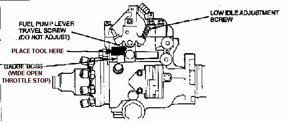
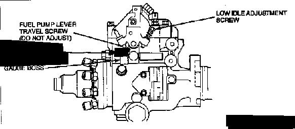 The vacuum gauge should read 6-8 in/HG. If it does not, loosen the VRV screws and adjust the VRV so the gauge reads 7 in/HG. If this reading cannot be achieved, replace the VRV and restart this procedure. After adjusting the VRV, remove the spring, apply and maintain 20 in/HG of vacuum to the VRV and cycle the throttle 5 times. The vacuum gauge should read at least 13 in/HG at idle position. If it does not, replace the VRV and repeat this procedure.
 The beeping should become a steady tone. If it doesn't, loosen the FIPL sensor (T-15 torx screws) and adjust to get a steady tone; a faster beeping occurs when the the FIPL is set too low.
dieselmann's Store"
IDI Parts
Back to dieselmann's IDI Page 1
Back to dieselmann's Page
WWW.Ford-Diesel.Com; The Ford Diesel Website--information and discussion for Ford diesel owners.
forddiesel Mail List
For the owners of Ford trucks and vans with the popular Navistar series of diesel engines ranging from 6.9s tp powerstrokes!
Diesel Injector Service;
For all of your diesel engine needs:
When it comes to Ford F250 parts AmericanTrucks has the parts to help your truck last longer and perform better.

![]()
Questions or comments:
![]()
 ©
© ©
©